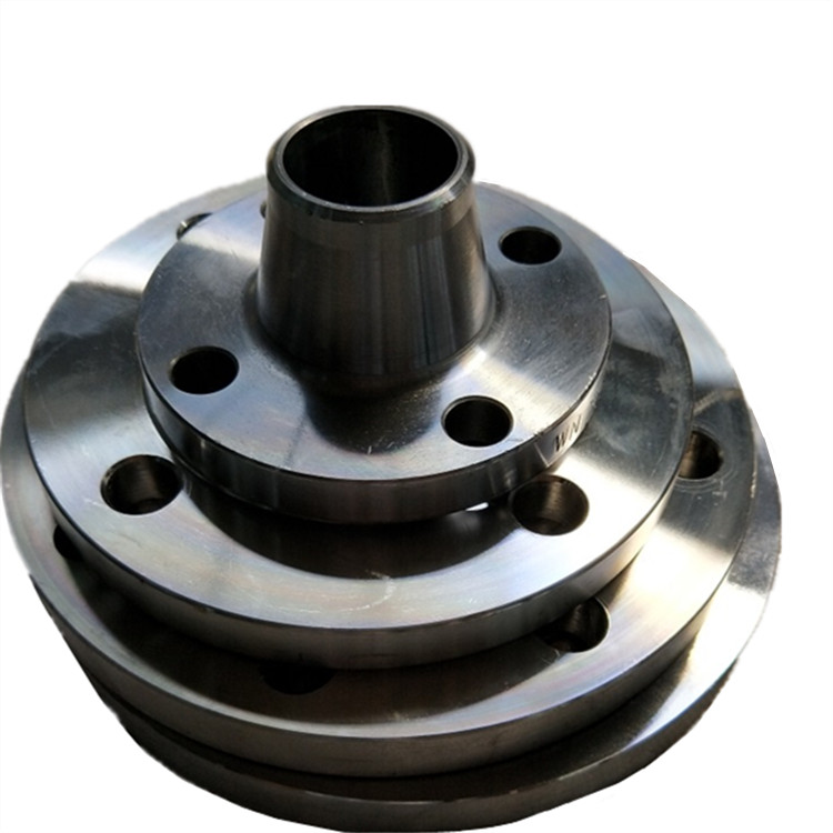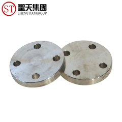


Also referred to as a screwed flange by any Threaded Flange Manufacturer, these flanges have a thread inside the flange bore. These threads aid the flange to be fitted onto a pipe, which in turn will have a set of matching male threads. Generally, a threaded flange is designed with the intention of being used in those areas that do not permit welding to be performed in the pipe area. For instance, if welding were to be carried out in highly flammable areas, the result would lead to explosions and potential health hazards. Hence, 1/2 threaded flange is used in nuclear power or heavy oil refineries. Apart from proving to be an easy and speedy connection device, it is important to note that a Carbon steel threaded flange is not particularly suited to perform well in industries that have a high temperature and a high pressure setting.
Specifications of ANSI B16.47/ASME B16.47 Threaded flange
|
Threaded flange Standards |
ANSI/ASME B16.5, B16.47 Series A & B, B16.48, BS4504, BS 10, EN-1092, DIN, ANSI Flanges, ASME Flanges, BS Flanges, DIN Flanges, EN Flanges, GOST Flange, ASME/ANSI B16.5/16.36/16.47A/16.47B, MSS S44, ISO70051, JISB2220, BS1560-3.1, API7S-15, API7S-43, API605, EN1092 |
|
Threaded flange Size |
1/2″ (15 NB) to 48″ (1200NB) DN10~DN5000 |
| Application | Petroleum industry, Refinery Company, fertilizer industry, power station, shipbuilding,onshore platform |
|
Threaded flange Pressure |
Class 150 LBS, 300 LBS, 600 LBS, 900 LBS, 1500 LBS, 2500 LBS |
|
Types Of Threaded flange |
Forged / Threaded / Screwed / Plate |
|
Special design |
As per your drawing |
Dimensions Of ANSI B16.47/ASME B16.47 Threaded flange
| Pipe Size | Outside Diameter of Flange | Diameter of Raised Face | Thickness of Flange | Diameter of Hub at Base | Length of Hub | Minimum Thread Length | Number of Bolt Holes | Approx. Weight |
| (NPS) | A | B | C | J | L | N | (Lbs.) | |
| 1/2 | 3 1/2 | 1 3/8 | 7/16 | 1 3/16 | 5/8 | 5/8 | 4 | 2 |
| 3/4 | 3 7/8 | 1 11/16 | 1/2 | 1 1/2 | 5/8 | 5/8 | 4 | 2 |
| 1 | 4 1/4 | 2 | 9/16 | 1 15/16 | 11/16 | 11/16 | 4 | 2 |
| 1 1/4 | 4 5/8 | 2 1/2 | 5/8 | 2 5/16 | 13/16 | 13/16 | 4 | 3 |
| 1 1/2 | 5 | 2 7/8 | 11/16 | 2 9/16 | 7/8 | 7/8 | 4 | 3 |
| 2 | 6 | 3 5/8 | 3/4 | 3 7/16 | 1 | 1 | 4 | 5 |
| 2 1/2 | 7 | 4 1/8 | 7/8 | 3 9/16 | 1 1/8 | 1 1/8 | 4 | 7 |
| 3 | 7 1/2 | 5 | 15/16 | 4 1/4 | 1 3/16 | 1 3/16 | 4 | 8 |
| 3 1/2 | 8 1/2 | 5 1/2 | 15/16 | 4 13/16 | 1 1/4 | 1 1/4 | 8 | 11 |
| 4 | 9 | 6 3/16 | 15/16 | 5 5/16 | 1 5/16 | 1 5/16 | 8 | 13 |
| 5 | 10 | 7 5/16 | 15/16 | 6 7/16 | 1 7/16 | 1 7/16 | 8 | 15 |
| 6 | 11 | 8 1/2 | 1 | 7 9/16 | 1 9/16 | 1 9/16 | 8 | 19 |
| 8 | 13 1/2 | 10 5/8 | 1 1/8 | 9 11/16 | 1 3/4 | 1 3/4 | 8 | 30 |
| 10 | 16 | 12 3/4 | 1 3/16 | 12 | 1 15/16 | 1 15/16 | 12 | 43 |
| 12 | 19 | 15 | 1 1/4 | 14 3/8 | 2 3/16 | 2 3/16 | 12 | 64 |
| 14 | 21 | 16 1/4 | 1 3/8 | 15 3/4 | 2 1/4 | 2 1/4 | 12 | 85 |
| 16 | 23 1/2 | 18 1/2 | 1 7/16 | 18 | 2 1/2 | 2 1/2 | 16 | 93 |
| 18 | 25 | 21 | 1 9/16 | 19 7/8 | 2 11/16 | 2 11/16 | 16 | 120 |
| 20 | 27 1/2 | 23 | 1 11/16 | 22 | 2 7/8 | 2 7/8 | 20 | 155 |
| 22 | 29 1/2 | 25 1/4 | 1 13/16 | 24 | 3 1/8 | 3 1/8 | 20 | 159 |
| 24 | 32 | 27 1/4 | 1 7/8 | 26 1/8 | 3 1/4 | 3 1/4 | 20 | 210 |