Introduction to concentric reducer

Views : 212
Author : admin
Update time : 2025-12-23 09:21:01

  In the design and construction of industrial pipelines, the need for pipe diameter changes is frequently encountered. Concentric reducers, as fittings specifically designed to address this need, have emerged to meet this requirement.

  I. What is a Concentric Reducer?

  ASME B16.9 Concentric reducers are specifically designed to connect pipes of different diameters, ensuring a smooth and efficient transition at the diameter change point. Their concentric design ensures that the pipe centerlines are on the same straight line, effectively reducing fluid resistance, turbulence, and pressure loss during transport, guaranteeing efficient and stable media delivery. They are widely used in various industrial fields such as petroleum, chemical, natural gas, power, and water treatment, and are an indispensable component in building reliable pipeline systems.

  A concentric reducer is typically a short, tapered pipe with different outer diameters at its two ends, smoothly transitioning from the smaller diameter end to the larger diameter end. The product is manufactured from high-quality steel, and the surface can be treated with anti-corrosion coatings (such as painting, galvanizing, 3PE, etc.) as required, resulting in a clean appearance and robust structure.

  II. ASME B16.9 Concentric Reducer Dimensions and Weight

  ASME B16.9 is a standard developed by the American Society of Mechanical Engineers (ASME) for factory-manufactured forged steel butt-welded pipe fittings. It is one of the important standards for the design, manufacture, and acceptance of concentric reducers.

  1. ASME B16.9 Concentric Reducer Dimensions

  Size Range: The standard covers a size range from 3/4 inch to 48 inches (DN20-DN1200). It specifies in detail the key dimensions for each size, such as the outer diameter of the reducing end and the distance from the center to the end face, ensuring the interchangeability of the fittings.

  Wall Thickness Selection: The wall thickness of the reducer is typically matched to the wall thickness of the pipe it is connecting to. Standard fittings are usually available in wall thickness grades such as SCH 10 - SCH 160, XXS, etc., and custom wall thicknesses can also be customized to meet different pressure rating requirements for specific projects.
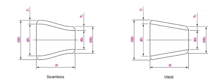

   Nominal Size

   Outside Diameter at Bevel

   Center to End
DN1 DN2 NPS1 NPS2 OD1 OD2 H
20 10-15 3/4 3/8-1/2 26.7 17.1-21.3 38
25 15-20 1 1/2-3/4 33.4 21.3-26.7 51
32 15-25 1 1/4 1/2-1 42.2 21.3-33.4 51
40 15-32 1 1/2 1/2-1 1/4 48.3 21.3-42.2 64
50 20-40 2 3/4-1 1/2 60.3 26.7-48.3 76
65 25-50 2 1/2 1-2 73.0 33.4-60.3 89
80 32-65 3 1 1/4-2 1/2 88.9 42.2-73.0 89
90 32-80 3 1/2 1 1/4-3 101.6 42.2-88.9 102
100 40-90 4 1 1/2-3 1/2 114.3 48.3-101.6 102
125 50-100 5 2-4 141.3 60.3-114.3 127
150 65-125 6 2 1/2-5 168.3 73.0-141.3 140
200 90-150 8 3 1/2-6 219.1 101.6-168.3 152
250 100-200 10 4-8 273.0 114.3-219.1 178
300 125-250 12 5-10 323.8 141.3-273.0 203
350 150-300 14 6-12 355.6 168.3-323.8 330
400 150-350 16 6-14 406.4 168.3-355.6 356
450 200-400 18 8-16 457.0 219.1-406.4 381
500 250-450 20 10-18 508.0 273.0-457.0 508
550 300-500 22 12-20 559.0 323.8-508.0 508
600 300-550 24 12-22 610.0 323.8-559.0 508
650 350-600 26 14-24 660 355.6-610.0 610
700 350-650 28 14-26 711 355.6-660.0 610
750 350-700 30 14-28 762 355.6-711.0 610
800 500-750 32 20-30 813 508.0-762.0 610
850 550-800 34 22-32 864 559.0-813.0 610
900 550-850 36 22-34 914 559.0-864.0 610
950 600-900 38 24-36 965 610.0-914.0 610
1000 700-950 40 28-38 1016 711.0-965.0 610
1050 700-1000 42 28-40 1067 711.0-1016.0 610
1100 800-1050 44 32-42 1118 813.0-1067.0 610
1150 850-1100 46 34-44 1168 864.0-1118.0 711
1200 900-1150 48 36-46 1219 914.0-1168.0 711


  2. Theoretical Weight of Concentric Reducers The weight of concentric reducers mainly depends on the material density, diameter, and wall thickness. The following is a table of theoretical weights for the products; actual weights may vary slightly depending on the manufacturer's process.


Large End
Nominal Size
Sch20 Sch30 STD Sch40 Sch60 XS Sch80 Sch100 Sch120 Sch140 Sch160 XXS
DN NPS
20
25
32
3/4
1
11/4
0.06
0.12
0.16
0.07
0.14
0.19
0.07
0.14
0.19
0.09
0.18
0.25
0.09
0.18
0.25
0.12
0.24
0.32
0.15
0.31
0.45
40
50
65
11/2
2
21/2
0.25
0.37
0.79
0.29
0.46
0.85
0.29
0.46
0.85
0.38
0.63
1.12
0.38
0.63
1.12
0.51
0.93
1.46
0.70
1.20
2.00
80
90
100
3
31/2
 4
0.97
1.28
1.45
1.11
1.52
1.81
1.11
1.52
1.81
1.50
2.09
2.51
1.50
2.09
2.51
-
-
3.18
2.09
-
3.76
2.71
-
4.60
125
150
200
5
6
8
-
-
5.57
-
-
6.16
3.04
4.35
7.12
3.04
4.35
7.12

-

 -

8.88
4.33
6.55
10.8
4.33
6.55
10.8

-

 -

12.7
5.63
8.35
15.1
-
-
16.9
6.86
10.4
18.6
8.02
12.2
18.0
250
300
350
10
12
14
8.18
11.1
24.6
9.99
14.6
29.5
11.8
16.5
29.6
11.8
17.8
34.3
16.0
24.3
46.0
16.0
21.8
39.0
18.8
29.5
57.4
22.5
35.7
70.8
26.0
41.7
81.5
30.4
46.5
92.0
33.7
53.3
102
30.4
41.7
-
400
450
500
16
18
20
30.5
36.8
65.5
36.5
51.3
86.7
36.6
44.1
65.5
48.3
65.3
102
62.7
86.2
138
48.3
58.3
86.7
79.7
107
174
96.2
130
213
112
152
247
130
171
284
143
193
316
550
600
650
22
24
26
72.2
78.9
136
95.6
117
-
72.2
78.9
103
-

143 

 -

164 

 199 

 -

95.6
105
136

209

 247 

-

252 

 306 

 -

294 

 358 

 -

336 

 402 

 -

376 

 452

-

700
750
800
28
30
32
147
157
168
183
196
209
111
119
127
-
-
230
147
158
168
850
900
950
34
36
38

179

 189 

 -

223

 236 

 -

135
143
151
245
282
-
179
190
200
1000
1050
1100
40
42
44
159
167
175
211
222
232
1150
1200
46
48
213
222

283 

296

Related News
Read More >>
GOST 12820 Steel Plate Flanges GOST 12820 Steel Plate Flanges
Jun .25.2026
GOST-12820 is standards for steel plate flat welding flanges formulated by the Russian Standardization Organization. It is applicable to pipe and valve connections.
DIN2573 PN6 Plate Flange DIN2573 PN6 Plate Flange
Jun .23.2026
DIN2573 PN6 Plate Flange dimensions of this standard can be used at maximum 120°C temperature with up to 6 bar of working pressure.
GOST 12836 Blind Flange Dimensions PN40 4.0Mpa GOST 12836 Blind Flange Dimensions PN40 4.0Mpa
Jun .16.2026
GOST Flanges are flanges manufactured according to the standards set by the Russian State Standard (GOST), which defines the specifications for flanges used in various industries, particularly in Russia and other former Soviet states.
ANSI/ASME B16.5 Slip On Flange Dimensions ANSI/ASME B16.5 Slip On Flange Dimensions
Jun .11.2026
ANSI/ASME B16.5 Slip On Flange Dimensions