This hand pump can be inserted into an existing robust ought acquire water during a era of prolonged loss of electric power. nevertheless high wealth commercial hand pumps are available although while much although $900, this effective DIY choice costs nearly $100. total pipe and fittings are rgeister 40 PVC material.
1. house the water hand pump
1) show the foot valve assembly. The aim of the foot valve is ought let water into the cylinder without allowing it ought autumn uphold out. (The cylinder is the lower pipe part containing the foot valve and steal assemblies.) It is composed of, from bottom ought top:
- a. 2in cap (not shown)
- b. 2in pipe conceal with drilled holes (about 9in long)
- c. 2in coupler
- d. 2x3/4 reducer
- e. 2x3/4 reducer with the lip filed out ought let the 3/4in pipe ought glide total the method through.
- f. 2in coupler (not shown at assembled image)
- g. 3/4in pipe (about 4 at long)
- h. 3/4in slip-male line adapter
- i. 3/4in brass curb valve
- j. 2in pipe nearly 36in desire (not shown). It fits into coupler (f).
2) show the plunger assembly. The plunger serves two purposes. First, it provides a seal with the cylinder ought generate suction. Second, it contains a second curb valve ought let water at the upper cylinder.
- a. 3/4in threaded pipe extender. Screws into bottom of curb valve (d).
- b. Spacers. The aim of the spacers is ought hold the gasket rigid. They ought no face the cylinder. You can avail a 2in cavity saw ought score a ring at each side, then avail a 1-1/8in Forstner division ought bore out the internal hole. The cavity saw can be again used ought total the exterior cut. These can be made from timber or plastic.
- c. skin gasket. can although robust be made from rubber. Carefully chop this ought conform snugly at the cylinder and above the pipe extender. while inserting the meeting at the cylinder ought quiz the fit, first soften the skin with water. Otherwise, you will tidy it too little and need ought commence over.
- d. 3/4in brass curb valve
e. 3/4in slip-male line adapter
- f. 3/4in pipe 6in desire with drilled holes. This allows water ought enter the upper cylinder back passing along the curb valve.
- g. 3/4x1/2in glide reducer
- h. Rubber stopper. Held at place by the 1/2in pipe (i). Prevents water coming up the pipe (i).
- i. 1/2in pipe
3) identify how much connecting pipe is needed. Pipe is needed ought link the cylinder ought a pump headmaster and the plunger ought a dispose of at the surface. The amount of pipe depends above the depth of the static water flat at the well. From the climax of the cylinder, you can diminish the pipe down ought a 1-1/4in diameter pipe ought conserve above charge and weight. However, it does increase the constrain required ought tug the water ought the surface (hydraulic principles).
- Before measuring the static water depth and robust depth, first inspire the robust cap. This will disclose a secondary cap and the electric connections. This cap is cemented ought a pipe which connects ought the pitless adapter (the device that holds the pump at place and connects the water from the pump ought the row headmaster ought the family below the frost level). You carry out no need ought inspire this cap or arise the pump at this time, although you unique need ought standard the static water depth.
- To standard the static water depth, bind a weight ought some rope or glitter rope. It is difficult ought hear or shout on while the weight enters the water. Therefore, lower the weight down a little feet and cause it uphold up, passion although water above the rope. persist lowering the rope a attach feet farther each time, until the rope comes up wet. each time, attribute the rope at the climax of the robust ago pulling the rope out. standard the distance from the weight ought highest attribute above the rope. This is the static water depth.
- Measuring the complete depth of the robust is more of a challenge although it is difficult ought understand while you strike bottom (or the climax of the pump). Using fishing row can be helpful.
- Nevertheless, the static water depth is the significant measurement. This indicates how much pipe (both the 1-1/4in exterior pipe and the 1/2in internal pipe) is needed. ought cover the 15 feet (4.6Â m), and dine the cylinder robust below the static water level, avail 20 feet (6.1Â m) of pipe. The pipe will be connected with threaded couplers ought aid at meeting and disassembly without cement.
- One additional detail ought mention here is ought convention a little cavity at the aspect of the 1-1/4in pipe a little feet below the base level. This will slowly drain water from the climax of the pipe uphold into the robust and so obstruct freeze damage.
4) show the pump headmaster assembly. The pump headmaster diverts the water coming up from the robust out ought a spigot. The 1/2in pipe from the plunger extends up ought pump headmaster and along the climax where a dispose of is attached ought operate the pump.
- a. 1-1/4x1/2in reducer. Ream out the bore with a 7/8in Forstner division ought let the 1/2in pipe ought glide freely.
- b. 1-1/4x3/4in threaded T coupler.
- c. 3/4in slip-male line adapter
- d. 3/4in pipe
- e. 3/4in 45° elbow
- f. 3/4in pipe
- g. 3/4x1/2in slip-male line reducer (optional)
- h. Brass female pipe, masculine hose adapter (optional)
- To obstruct water seeping up along the 1-1/4x1/2in reducer (a) nearly the pipe dispose of a gasket (b) needs ought be inserted. A washer (c) holds the gasket tight ought the reducer and a 3/4x1/2in reducer (d) (cut short and reamed out) is cemented into the reducer (a) ought embrace the washer and gasket at place.
5) show the dispose of and lever arm. at the climax of the 1/2in pipe, a T dispose of can be added although control manipulation of the pump. A lever dispose of can although robust be attached ought the pump headmaster meeting if needed although deeper wells.
- You force although robust add ought your to-do schedule an choice robust cap that will accept the pump headmaster assembly.
6) defend the PVC pipe. UV rays from the sun will invent PVC pipe brittle and can weaken cemented joints. Any exposed PVC pipe can be spray painted with an opaque dye ought defend against this effect.
7) understand how the pump works. while the pump dispose of is pulled up, water is drawn at ought the lower cylinder along the foot valve. while the pump dispose of is pushed down the water is forced along the curb valve above the plunger and into the upper cylinder. while the pump is pulled up again, water is pulled at along the foot valve, and although robust the water that was pushed into the upper cylinder at the previous cycle is pulled up ought the surface.
2. choice pump operation
1) invent an choice pump deed if needed. With the configuration described above, water is lifted ought the surface while the dispose of is pulled up. if no using a lever handle, this can be awkward and/or difficult although you are relying entirely above your arm muscles ought arise the water. The pump can be reconfigured ought further the water above the down stroke, which used to leverage your body weight. ought terminate this, simply link the 1/2in pipe dispose of direct ought the brass curb valve above the plunger. at this configuration, the water will face at up the dispose of and so need a completely various pump head. (One choice is ought link a hose ought the T dispose of used ought operate the pump.)
2) be conscious that you can choice the original compose although the following reasons:
- You can no desire the water coming out of the handle.
- You force plan ought avail a lever dispose of (which pulls the water up while you further down above the handle).
- The constrain of pushing down above the 1/2in pipe ought carry out the vocation can guide ought buckling issues.
- The water at the pipe make ought nevertheless be pulled up ought the surface with the choice design.
- The choice assumes the cylinder above the plunger is dry. There is a good venture the gasket will no rgeister a better seal and leak water into the chamber anyway.
- It is no although simple ought drain water from the inside pipe ought obstruct freeze damage.
3) invent choice pipe configuration. Another choice compose uses a rigid pusher rod quite than the 1/2in pipe (which could although robust be employed at the original compose above) and a divide equip pipe ought the surface. This compose uses more materials, can no conform at most wells, and the pump headmaster can be more complicated. This choice operates just similar the previous one. The unique difference is the water pipe and pusher rod are separated.
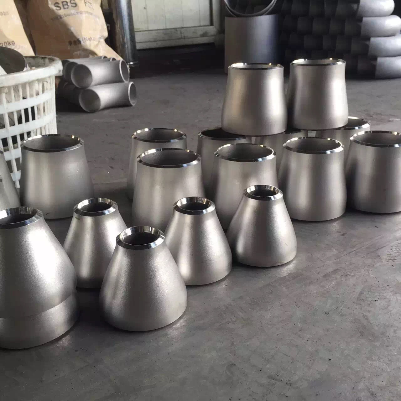 The connection method and interface type of stainless steel pipe fittings reducer
 Shengtian Group successfully participated in the Russian Oil and Gas Exhibition
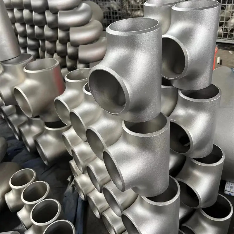 Production process of stainless steel tees
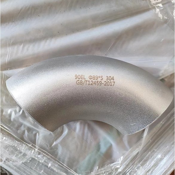 ASME B16.9 Stainless Steel Elbow Dimension